Chapter 3.6
Safety switches
Doors, lids and covers must be monitored to ensure the machine control system can stop movements before a person enters a hazard zone. The safety switches used for monitoring are often also referred to as guard, door safety or position switches. Throughout this chapter we will guide you choosing the right safety switch.
Rules for safety switches
The switches fitted to guards are called interlocking devices in standards and come in four types. These switches are critical for safety, especially on high-risk guards. They must be installed securely to prevent unauthorized access and ensure proper operation.
1. Switches that are mechanically actuated by a rail, plate, or cam on the guard or even by the door itself. Popular types are the roller lever, roller plunger and hinge switches. These switches are all uncoded and require significant design and assembly effort, which is why they are rarely used today
If you use them, ensure the following:
- The switches are installed securely and cannot shift from their position due to improperly tightened screws. Use locating pins or notches on the switch to prevent maladjustment which could lead to premature switching or no switching at all.
- Fasten the switch so it cannot be demounted with standard tools. For example, consider using one-way screws, rivets or a hole drilled in the screw heads.
- On guards for high risk situations, be sure to use two switches with opposite switching logic (one closing, one opening when the door is opened)
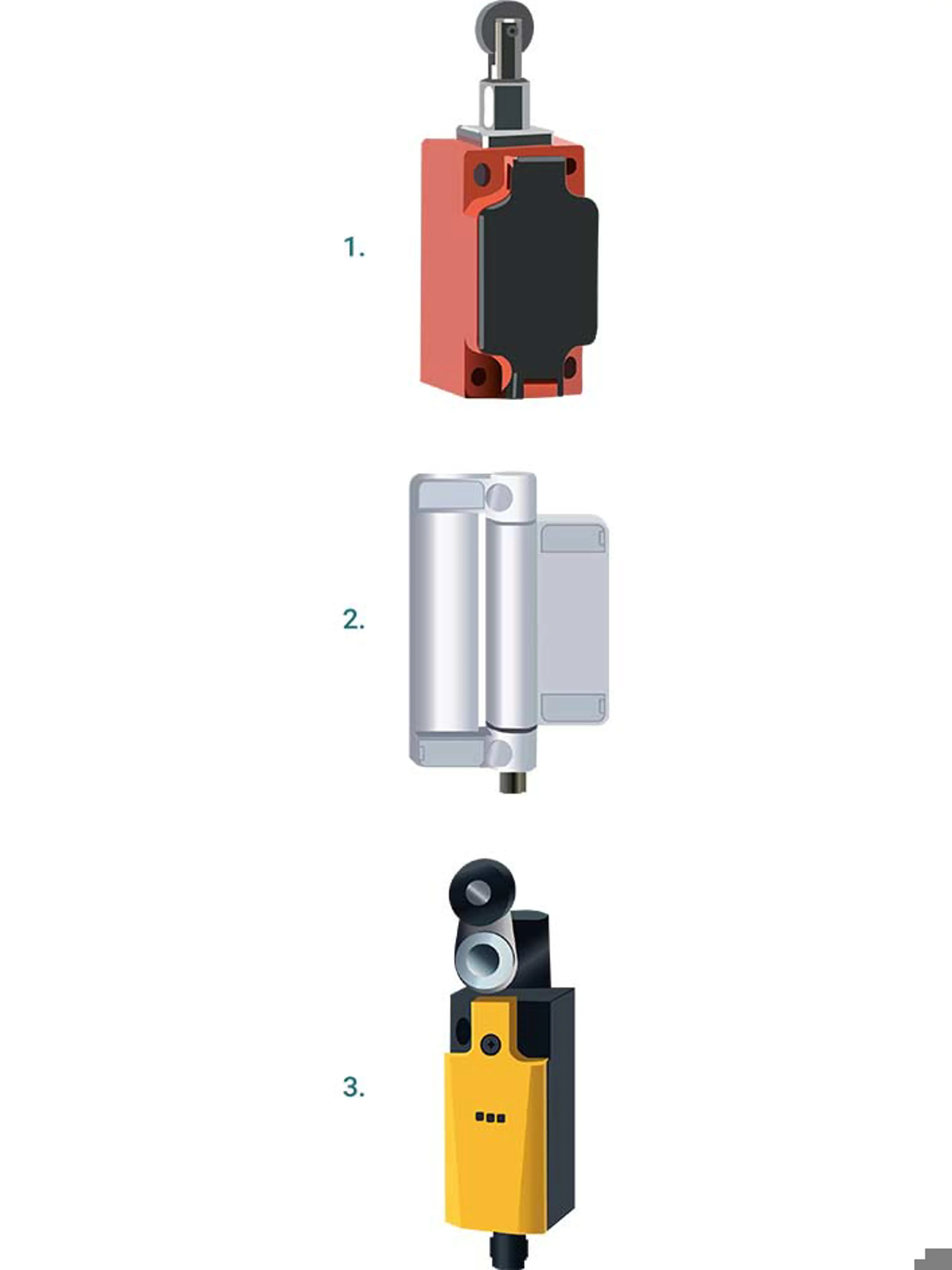
2. Switches that are actuated by a mechanic mating piece or key, known as the actuator, are still the most used safety switches today. They are easy to install and come in single or double channel technology. Many switches can also be set up or supplemented for guard locking, which keeps the guard securely closed using a magnetically powered pin or lever.
Unfortunately, these safety switches with separate actuator are vulnerable to manipulation. Simply removing the actuator from the door and inserting it into the switch allows the machine to operate with the door open.
To prevent this manipulation:
- Use switches with coded actuators (not every actuator fits every switch). However, limited coding options may still pose a manipulation risk.
- Ensure that the actuator cannot be removed with standard tools by using one-way screws, rivets, or drilling holes in the screw heads.
- If there is no coding or only low/medium coding (less than 1000 different codes), install the switch so the actuator cannot be plugged in when the door is open. Alternatively, hide the switch from the operator. Both options are challenging to implement and may require significant engineering effort, making them feasible primarily for series-manufactured machinery.
3. Proximity switch, uncoded. These switches are similar to mechanical ones with separate actuators. However, instead of being actuated mechanically, they are triggered electronically when the actuator is near the switch. For guard locking, an additional mechanical lock is required and many switch manufacturers offer both functions in a single unit. Like the uncoded mechanical switches, uncoded proximity switches are easily manipulated, and the additional requirements mentioned under switch type 2 therefore apply to them..
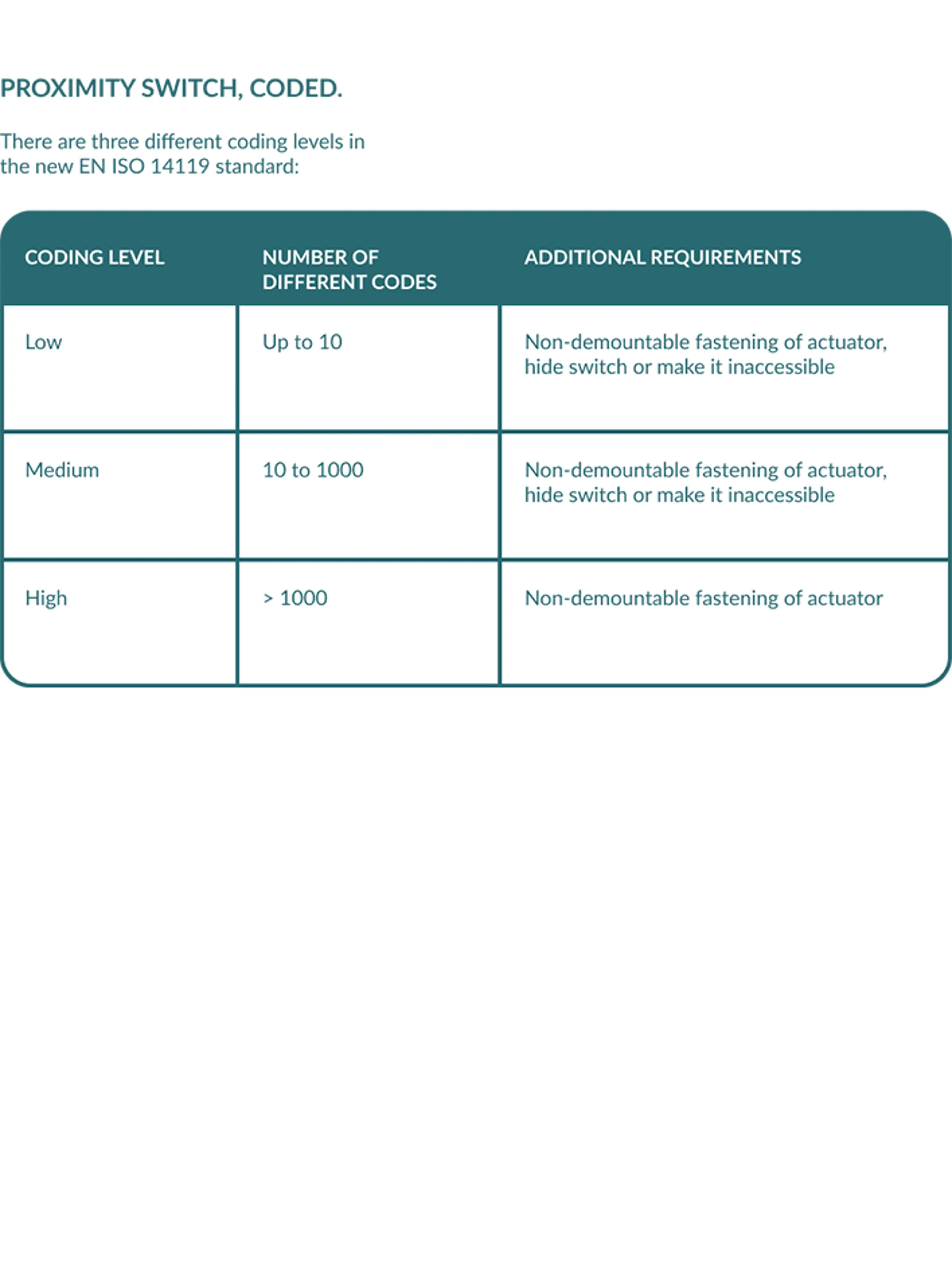
4. Proximity switch, coded. In the (EN) ISO 14119 standard, which is referenced in ANSI B11.19 for the USA and CSA Z432 for Canada, three different coding levels for these switches are identified, as listed in the chart.
Key transfer system
Interlocking of operating modes and doors
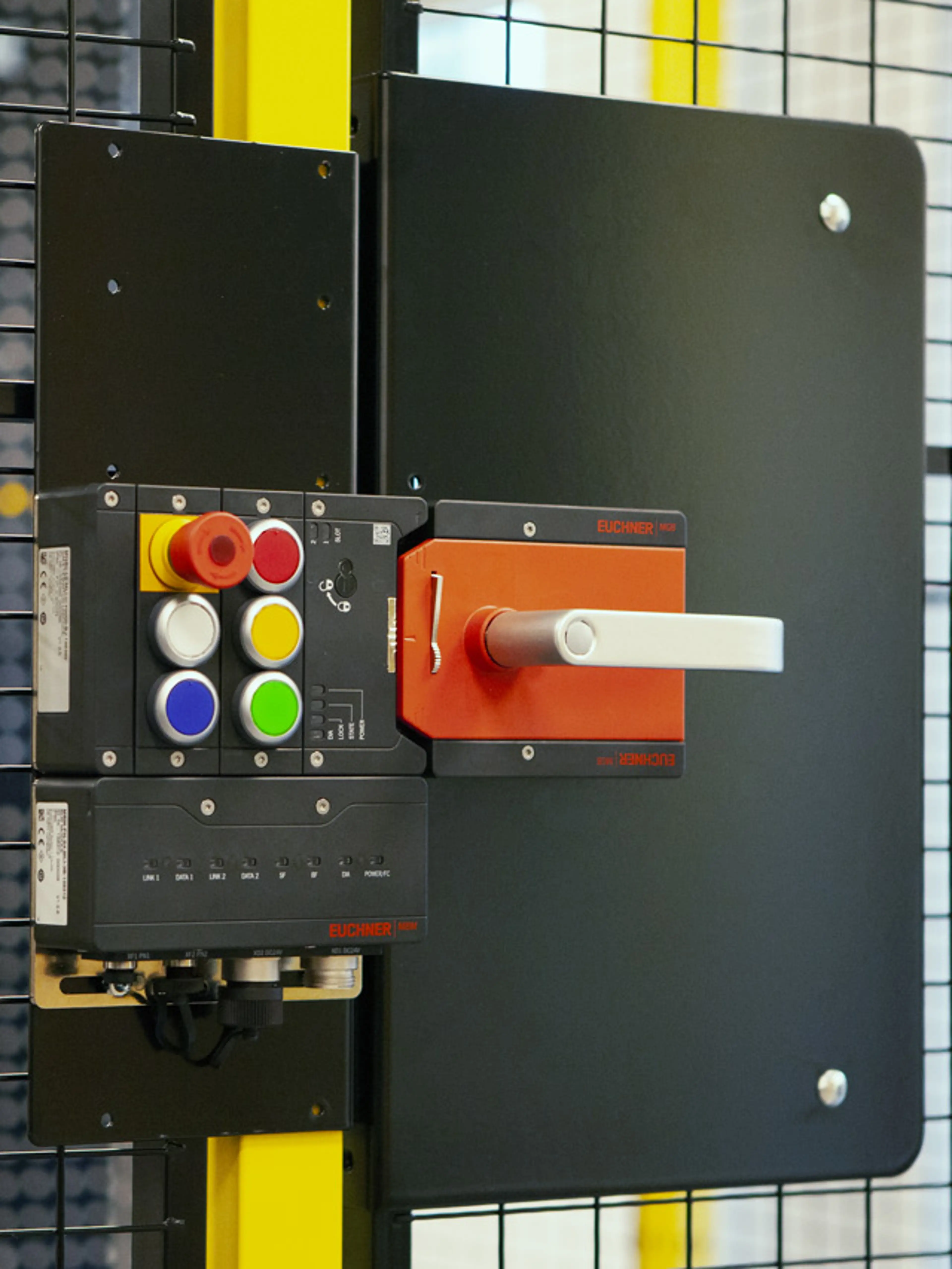
In many applications, operator access to a hazard area must be prevented as long as a machine is powered. This can be achieved by movable guards in connection with mechanic/electromechanic interlocking. A long-standing technology in this field is the so-called key transfer system also referred to as a "trapped key system" in the USA and the UK.
Basic function of a key transfer system
A long standing technology in this field is the so called key transfer system also referred to as a "trapped key system" in the USA and the UK.
- A door opening key is trapped in a control box at the machine until the machine is switched off (illustrated below, number 1 and 2).
- Then the key can be removed and used to open a locked guard on the machine (illustrated below, number 3 and 4).
- As long as the guard is not closed and locked, the key is trapped in the guard, preventing the machine from being powered up (illustrated below, number 5).
Such key transfer sets come with high level coding and therefore reliably prevent manipulation of the guard.
There is a wide variety of options for key transfer systems:
- The key may release several other keys for different doors.
- The key may also be used to enable operation of a switch for safe shut-down of a machine section etc.
- The operating sequence can be controlled closely and delays be integrated to allow machinery to come to a complete standstill before access.
- Electronic keys may be used, which are presence-sensed.
- Electronic keys may not switch the machine off completely, but enable some operating modes in the machine, while disabling others.
- Electronic keys may be assigned to staff with different qualifications and access right levels.
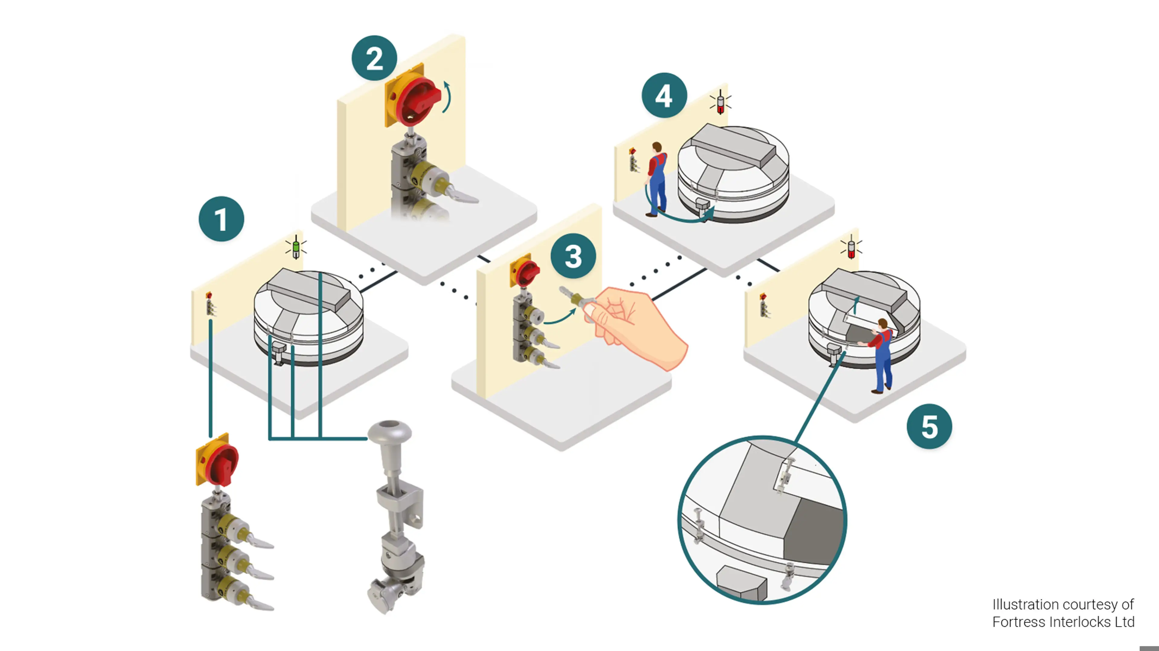
1 - Machine running | 2 - Main switch off | 3 - Trapped key removed | 4 - Trapped key transferred to machine cover | 5 - Machine cover open, key trapped
Mandatory
Emergency stop switches/push-buttons
The emergency stop function must always be available and operational. It must not be considered an alternative to other required safeguards. The international standard for it is (EN) ISO 13850.
Emergency stop
An emergency stop is often misunderstood as a selectable safeguarding measure, but it is not.
An emergency stop is a function required in addition to other safeguards.
The Machinery Directive and Machinery Regulation both say:
“The emergency stop function must be available and operational at all times, regardless of the operating mode. Emergency stop devices must be a back-up to other safeguarding measures and not a substitute for them.” MD Annex I/MR Annex 3 section 1.2.4.3
The only exceptions are:
- The machine is hand-held and letting go of its control button will cause stop anyway.
- An emergency stop in a machine would not reduce the risk.
The stop categories
The emergency stop comes in two categories:
- 0 – The emergency stop causes immediate disconnection of all drives of hazardous movements from their energy sources
- 1 – The emergency stop causes a controlled stand-still of the drive (usually by applying brakes). It may also trigger a function achieving safety. Once the desired condition is reached, all drives are disconnected from their energy sources
EN/IEC 60204-1 also describes a stop category 2, but it must not be used for emergency stop.

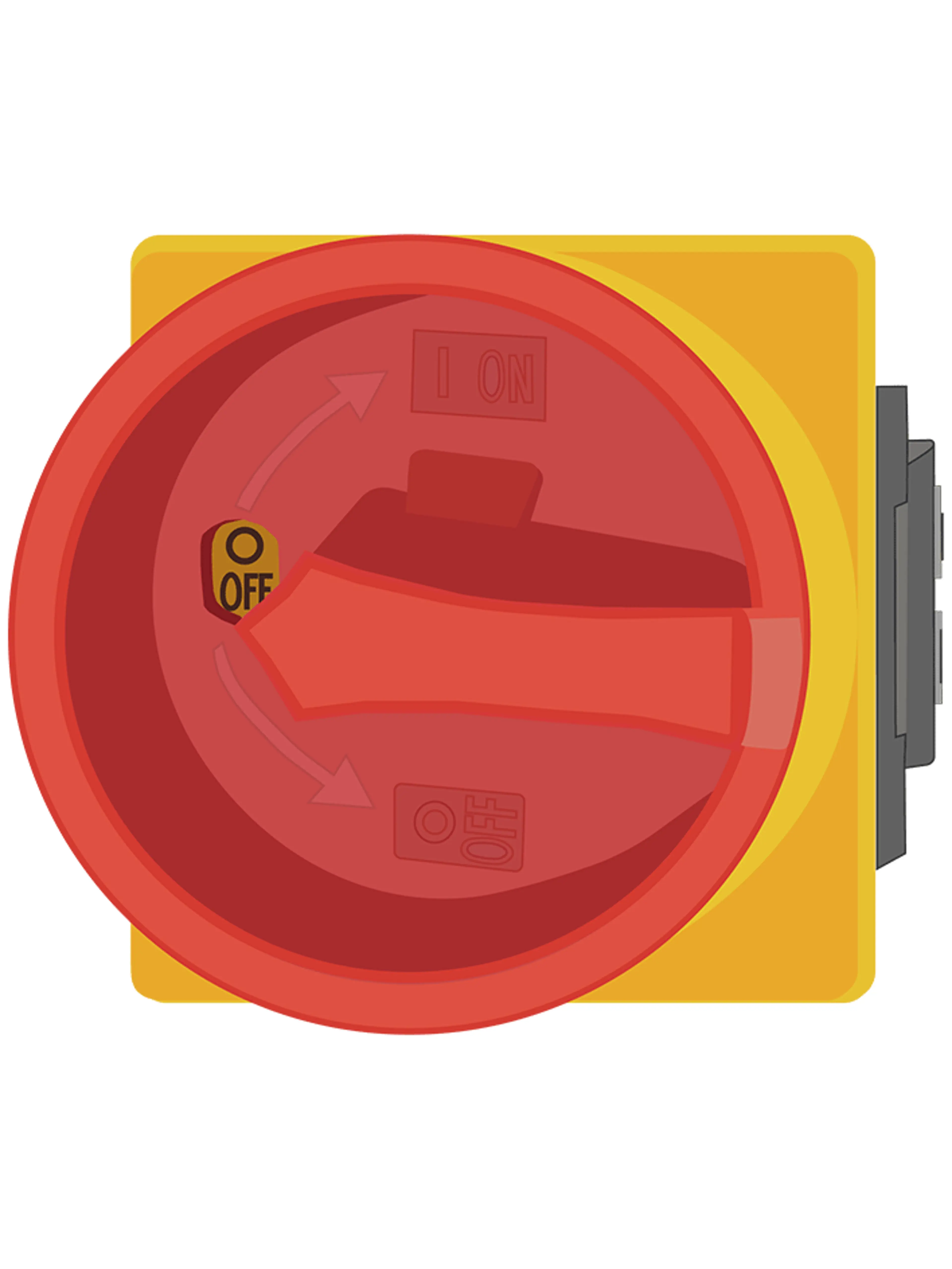
Emergency switching off
This term is not used very often. It refers to an emergency stop circuit with electromechanical components only.
Until the late 1980s all safety-related control functions were achieved with electromechanical switchgears.
However today we are using all kinds of electronic and microprocessor-controlled safety devices, so a clarification concerning how an emergency stop should function became necessary.
Emergency switching off is different from emergency stop in two ways:
- It is always in stop category 0 - Immediate disconnection (see image)
- It must use electromechanic equipment only (no electronics and software allowed)
Normally, the only emergency switching off device on machinery today is the main switch. If it is meant for use in case of emergency, then it must be coloured red and yellow. If the main switch is not red and yellow, then it must not be switched off in case of emergency, as this could prevent the braking of hazardous movements for example.